Hi all, hope everyody is well.
I got a bit more done last night, but didn't all go to plan - you'll see below! I was planning to get another bit done tonight but for some reason my 3 1/2 year old son has only just gone to bed, the wife went ages agio and left me with him! Normally he's asleep by about 19:30 and it's 22:55 now!
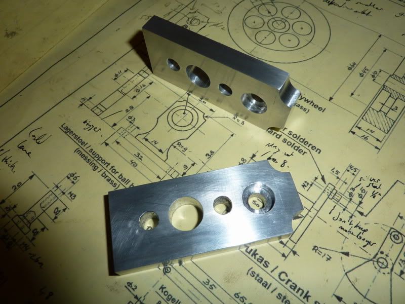
I wanted to get the bearing housings done, these were to be done from aluminum plate. Again, I am simplifying Jans design slightly. Mine will have no support pillars and are a simple rectangular shape to save time.
Started by marking out the outline something I have rarely done before, even used marking blue!
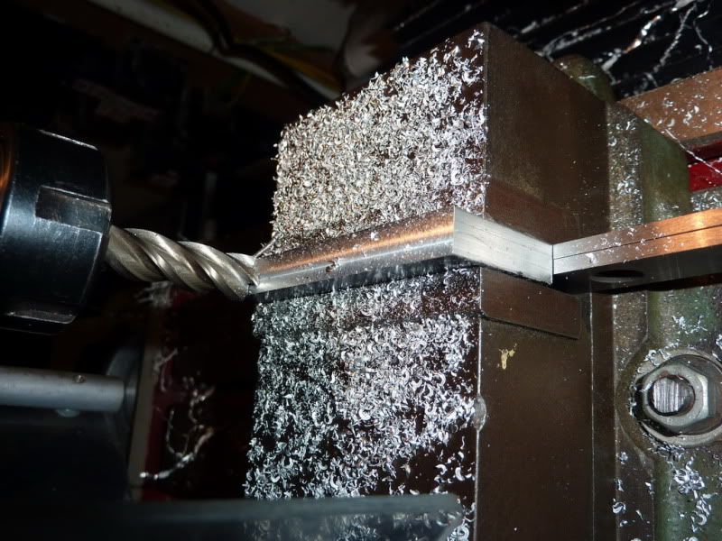
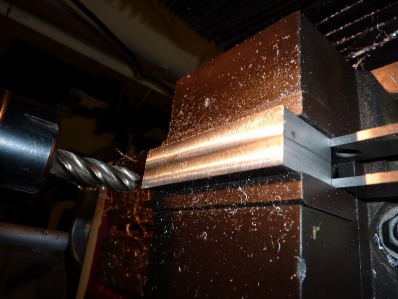
I was planning to cut the flat bottomed recess for the ball races with a 12mm end mill. But then I remembered when I tried that on the hot air engine, the hole it produced was much bigger than the bearing! That was in my old mill, with old cutters though. Nevertheless I decided to do a test run on a bit of scrap:
You can see that the hole produced is quite a bit too big, a very loose fit. So I set about measuring other end mills I had to see if one was just undersize there was one, but I tried that and it was no good too small!
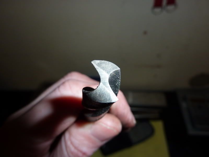
So I found a drill that was just a little undersize, 15/32 I think ~11.91mm. I ground it flat and put a couple of reliefs on it, did the test and it seemed to cut ok so I would go with this. The fit on the bearings was a press fit.
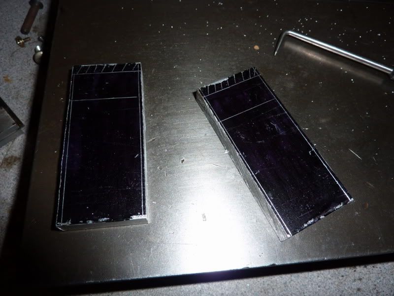
Back to the job in hand shaping the housings then:
Milling to width:
Put them together to ensure both the same width:
They ended up 0.1mm under the 30mm I decided on but it really doesnt matter! Being the same size is more critical.
Took a skim off the bottom face of both at same time are end mills meant to be used like this? It doesnt seem give the best or flattest finish.
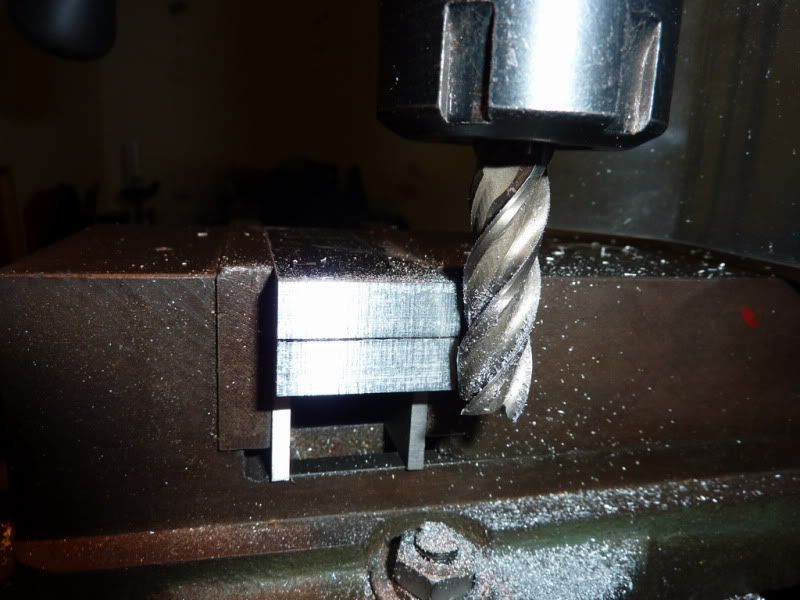
Started milling the other end to length but I didnt like using the side of the cutter like this:
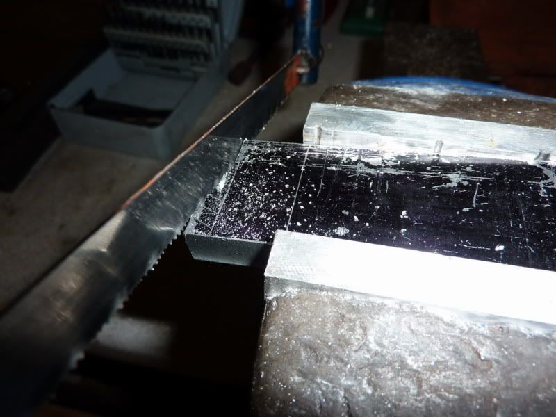
There was a few mm to take off so I sawed the excess off first:
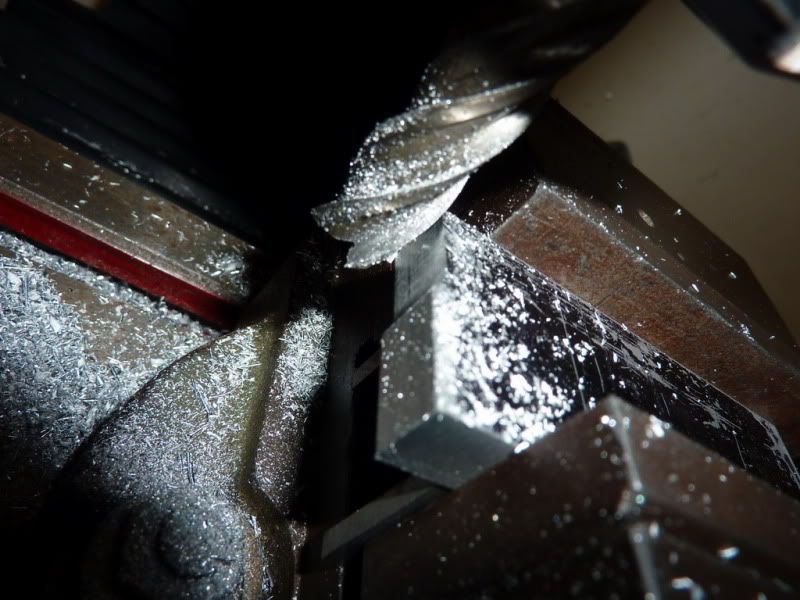
Then milled both at once like this to ensure both the same length / height:
I liked this marking out lark, it was easy to see things and because the arrangement of holes Id decided on made it easy to confuse the two ends I decided to mark it out properly ish!
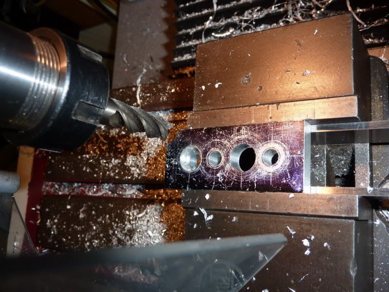
I then spend a good quarter of an hour decided what was the best procedure for drilling all the holes there were to be 2 x 6mm holes (just to make it not quite so boring), the 6.5mm hole behind the bearing to clear the 6mm crankshaft, the 12mm flat bottomed recess, and another 12mm decorative hole.
First off I decided Id just make all the holes 6.5mm to save swapping drills. Then I decided I could have drilled half the holes by now if Id just started!
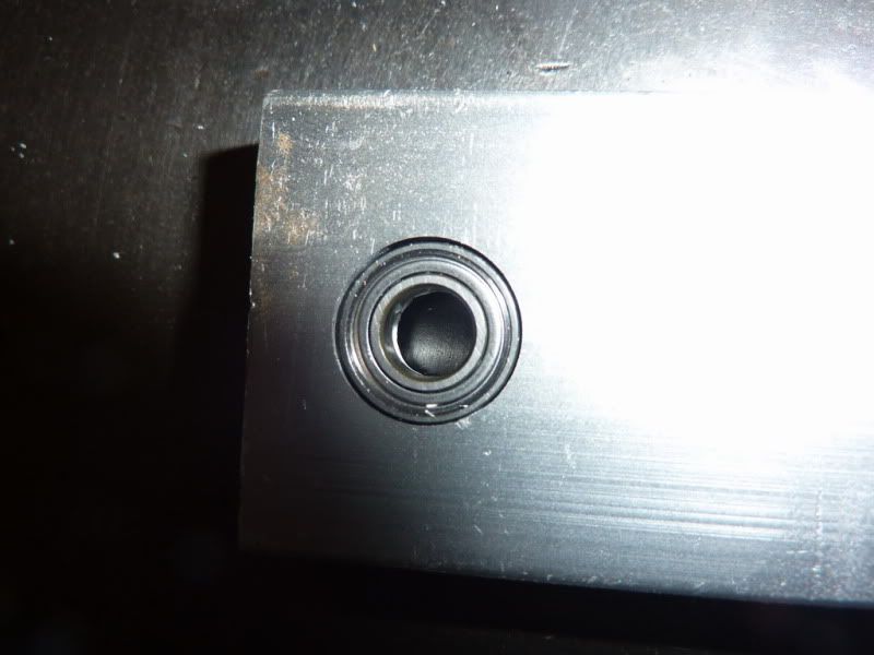
The recess looks not too bad considering its a bodged drill!
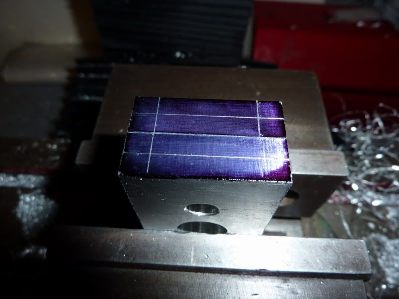
Finishing off with radiused corners I nearly always mess the part up doing this, it always seems to move in the vice. I should take little cuts instead of trying to plunge in 1 go. So I had to take another couple of finer cuts so it wont be quite to drawing but I came up with a method of getting them all the same using a parallel across the end of the vice jaws and flipping it over for the other edge. Im not even convinced it looks that good, it seems to have become one of my little trade marks! It just makes it a bit more pleasing on the eye
I think?!
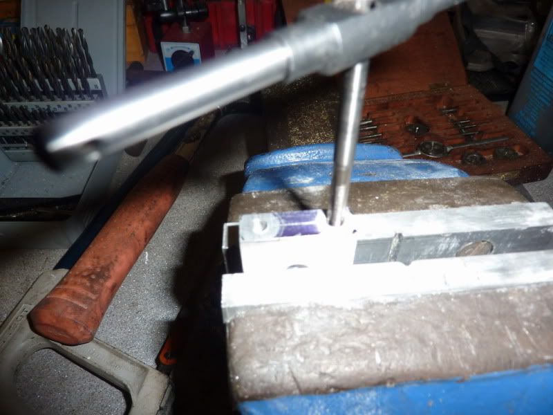
Jus the holes to drill and tap in the bottom. Im using 2ba. Again, I just marked them out and this time centre drilled then drilled.
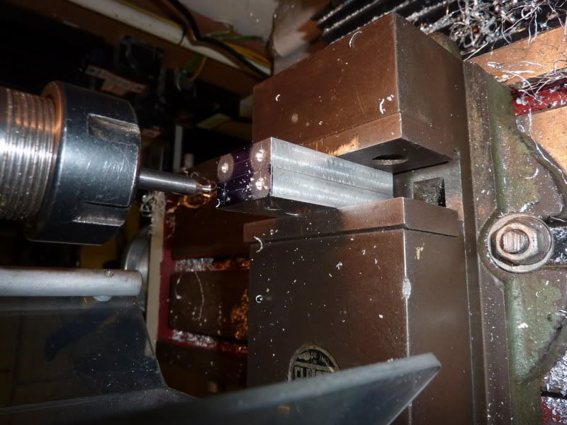
Finishing off the tapping in the vice once the taper tap had started the thread sufficiently:
I polished them on some wet and dry to try to get some of the nasty marks out. I hate polishing though so any I do is minimal. On the 2nd one I remembered that somebody recommended using white spirit as a cutting fluid on Aluminum so I tried it for tapping. Worked pretty well, so I did a final quick polish with some white and wire wool! It was to clean them more than anything theres little point in putting actual polish on it unless all the machine marks are gone now in my opinion and they arent. I have polished all the other items on the engine just with oil and wet & dry so far, gives a nice sort of engineering brushed type finish.
So, was quite happy with those, then I pressed the bearing in with the vice, but the press fit must have been too tight and it made the bearing bind up. Luckily when I got the bearing back out it sprang back to shape and is free again but I have probably done some damage to it. So I need to open up the recesses some how so the bearings are a nice sliding or push fit. I kind of knew this, I just assumed a press fit would be ok but I guess due to the small size of these it just compressed the outer ring.
I have thought of a couple of ways of doing this. Either chuck in 4 jaw in lathe and set it running true, then make a small boring tool from an old drill and bore out marginally. The trouble will be clocking it, I dont have a dti with the little probe that flicks out sideways. Could put something good fitting in the hole and clock it that way.
Another thing I thought of was making a tiny cutter with a grub screw and bit of HSS for the milling machine.
Or, I might get away with using the 12mm end mill in the lathe once clocked in 4jaw or even just hold the cutter in the vice and twist it by hand for the amount that needs to come out. Im guessing its the run out on the cutter that makes it cut larger.
Should be able to save them some how though as the holes are too small at the mo. Any other ideas?
Nick


