Author Topic: Another Halo  (Read 55528 times)

Offline shred

  • Jr. Member
  • **
  • Posts: 54
Re: Another Halo
« Reply #75 on: October 21, 2009, 10:37:43 PM »
Thought I'd posted my video of the PD engine running with the valve spool and all.. but it turned out the only posted video shows it running with the valve on, but not operation of the valve ltself.. sorry Bogs  :scratch:  

Anyway, kvom, those parts are looking good and the notes are very useful as well.  Keep it up.

« Last Edit: October 21, 2009, 11:23:51 PM by shred »

Offline kvom

  • Hero Member
  • *****
  • Posts: 520
Re: Another Halo
« Reply #76 on: October 29, 2009, 07:14:35 PM »
After a 4-day weekend offroading the Jeep and 3 more days doing various maintenance work, I finally had an afternoon in the shop to get back to the engine.

First I finished all of the remaining drilling on the 4 headers (I will need to remake the 5th).  Then I put one of them together completely along with the cylinder.  Here's a looksee:


Originally I was going to leave the valve cover thicker than the plans, as I had made them from .25" thick brass plate.  However, I needed to attach them with the shortest screws, so the options were to machine them thinner or cut the counterbores deeper.  FWIW, I milled the counterbores with a 3/16" endmill; the plans show using a 1/8" endmill, but since the head of the screw is larger than that milling the bores is more complicated/tedious.

Some of the brass plungers were a bit too large to fit the holes, even though I measured them at .125" and the holes were reamed with a .126" reamer.  Once they're machined they are a PITA to hold and polish down to size (I used a needlenose plier).  So a recommended alternative would be to make the heads first and test for fit on the lathe before parting off and machining the heads.

Next step is to clean up the interiors of the cam housing and crankcase, plus part off the crankcase and make some pistons.  Then it will be time for a trial assembly.  I also need to start thinking of a mount design.

Offline kvom

  • Hero Member
  • *****
  • Posts: 520
Re: Another Halo
« Reply #77 on: October 30, 2009, 09:36:27 PM »
I had another full afternoon in the shop.  Today I started with the pistons.  Chucking some 1/2" diameter aluminum rod, for each I turned 1/2" length down to .375 and individually fitted each to its own piston, trying to attain a rough sliding fit.  Then I parted each off,

To finish a piston, I chucked it in a 5C collet block with .25" exposed, then placed the block vertically in the mill vise.  I used an edge finder the first time to find the center.  First operation was to mill off the nub from parting and bring to length.


Then with a 1/8" endmill (1/16" for the master piston) I cut a slot .200" deep, then widened the slot .003" on each side with two more passes.


Then it was a simple matter to chuck the collet block horizontally and spot drill/drill the cross hole for the wrist pin.  Once removed from the collet and deburred, I was able to assemble the conrods to the pistons using the pins supplied by Liney.  The holes are not a press fit, but I doubt that's critical.  Here's a "family" portrait:


The pistons still need a bit of toothpaste lapping to slide smoothly.  I didn't cut any oil grooves but I did chamfer the tops of the pistons.

After smoothing the inside of the cam housing with Scotchbrite, I wanted to do a trial assembly of the front portion of the engine.   The first task was to machine the bearing carrier to its planned thickness of .125".   I had previously parted it off oversize and needed to removed .016" from the back.  To do this I decided to use my "new" chuck with soft jaws on the lathe.  I had made the jaws over a month previously, but this was the first opportunity to try it.

First, I machined a pocket .100" deep and 1.275" in diameter to match the part.  This allowed me to then chuck the disc securely and take the facing cut:


Now after deburring, I laid out the components for assembly:

Cam housing, front bearing, driveshaft, rear bearing, and bearing carrier:


The rear bearing is a tight fit to the bearing carrier:


Then screw the bearing carrier to the cam housing to complete the assembly:


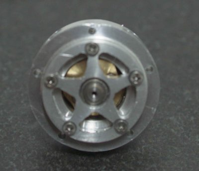
It's important that the bearing carrier press both bearing firmly against the driveshaft to eliminate any slack but not so that the "preload" causes binding.  I need to do some tweaking here.  I also noticed a few more issues to fiddle with.

1) The plunger holes are slightly too small for the supplied ball bearings to slide freely, so may need deburring or mild filing.

2) The rear cam seems a bit too far forward and may be interfering with the front plungers.  I may need to add a shim.

3) The crank is not sitting perfectly straight on the end of the shaft.  I suspect the counterbore bottom is not flat.  In any case, the thickness of the crank or depth of the counterbore can be modified to center the conrods under the cylinders, so I will hold off until I'm ready to fit the crankcase.

Offline chuck foster

  • Sr. Member
  • ****
  • Posts: 334
  • Country: ca
Re: Another Halo
« Reply #78 on: October 30, 2009, 11:07:38 PM »
looking good kvom  :thumbup: :thumbup:

there is allot of parts to this engine and they seam to be kinda small  :bugeye: but you are making it look easy.

cant wait to see this one run  :ddb: :ddb: :ddb:

chuck  :wave:
hitting and missing all the way :)

skype:  aermotor8

former hmem member

Offline Darren

  • Madmodder Committee
  • Hero Member
  • *****
  • Posts: 3795
  • N/Wales
Re: Another Halo
« Reply #79 on: October 31, 2009, 06:30:26 AM »
Looking good there Kirk, that looks like a fiddly engine with all those tiny bits,  :thumbup:
You will find it a distinct help… if you know and look as if you know what you are doing. (IRS training manual)

Offline kvom

  • Hero Member
  • *****
  • Posts: 520
Re: Another Halo
« Reply #80 on: October 31, 2009, 06:12:04 PM »
I had a couple of hours before the Halloween visitors start arriving to tweak the cam housing issues.

I discovered upon inspection that the front cam was not seating flat against the driveshaft flange.  With tight tolerances on all the parts, the clearance holes were not large enough to allow the screws to enter perfectly straight.  I drilled them out with a #43 drill as opposed to the original #42, and with some careful tightening both cams set flush.

Since the camming surfaces are so close to the inner diameter of the cam housing, it's important that the shaft and cams be as perfectly centered as possible.  How the bearing carrier is screwed to the housing is important, as it seems that the slightest cant in the carrier can cause the cams to rub.  So tightening the screws evenly all around going in circles was necessary.  I marked both the carrier and housing to ensure that any reassembly matches up the same set of holes.   When assembled, the bearing preload seems good, so I don't think any adjustment will be needed.

I cleaned up the pushrod holes, and now the supplied ball bearings and my brass pushrods fit nicely.

I also parted off the crankcase and turned the back flush, so that I can start thinking how to build a base.


Darren,

The size of the parts hasn't been as intimidating as I thought at first.  Having soft jaws on the lathe, vise, and rotab really helps, as otherwise clamping would be an issue on some things.  One fiddly issue for me is the size of the screws;  I have to be really careful not to drop any as there are not a lot of extras in the kit.

Offline NickG

  • Madmodder Committee
  • Hero Member
  • *****
  • Posts: 1890
Re: Another Halo
« Reply #81 on: October 31, 2009, 07:44:02 PM »
Yeah looks far too fiddley for me! Well done, can't wait to see this in action!
Location: County Durham (North East England)

Offline kvom

  • Hero Member
  • *****
  • Posts: 520
Re: Another Halo
« Reply #82 on: November 01, 2009, 08:41:48 PM »
Got into the shop around noon, and decided to verify that the pushrods would correctly activate the rocker arms and valves as designed.  The pushrods are just 1/16" drillrod 1.4" long, so I cut off a couple with wire cutters and filed the ends.  Here's the assembly with one cylinder:


It seems to work!  At least the plungers that activate the valves go up and down.  It takes a fair amount of force to turn the shaft with just fingers.  As Liney suggestes, I will need to attach a small chuck or the equivalent to turn it manually with all 5 cylinders mounted.  I may need fewer turns on the springs as well.

Given that assembling further without something to hold the engine securely would be difficult, I spent the rest of the session making the first part of an engine mount.  First, I took the piece of aluminum from which I parted the crankcase, faced it on the lathe, and then drilled and tapped 5 holes to match the rear mounting surface of the crankcase.


Next, I found a piece of aluminum plate that had a hole in a useable spot, and with the aid of a little trig and the DRO, I drilled holes to match the jig.


Then after enlarging the hole a bit on the mill, I mounted the plate on the jig...


... and milled the hole to match the innder diameter of the crankcase.


Successful test fit:


Some more milling, flycutting, on the rotab and vise yielded this:


A test fit of the crankcase and a couple of cylinders to show that there is clearance for air supply:


I won't be able to complete the mount until I get a propeller and determine the necessary height above the base, but this part will be very useful in assembling and testing.


Offline kvom

  • Hero Member
  • *****
  • Posts: 520
Re: Another Halo
« Reply #83 on: November 08, 2009, 08:24:53 PM »
Since I blew a start cap on the RPC this week, the lathe was out of operation until this weekend.  Once I got things back together, I finished remaking the crank, and it now sits square on the shaft.  I also managed to file the ends of the conrods so that they will assemble with the master rod and the crank pin.

So now comes the problem of assembly.  I discovered that there is no way to insert the assembled conrods/pistons with the cylinders attached.  So my plan is to insert the pistons into the clyinders with the conrods attached, and try to assemble the rods inside the crankcase.  If that proves too hard I can try it without the cylinders and and/or pistons, and then install the cylinders over the pistons.


Offline kvom

  • Hero Member
  • *****
  • Posts: 520
Re: Another Halo
« Reply #84 on: November 09, 2009, 06:20:23 PM »
After a lot of unsuccesful fumbling, I finally figured I would never get the conrods attached while they were in the crankcase.  So I disassembled everything, and was successful in pinning the rods together.


The pins themselves were a bit of a struggle: 1/16" drillrod .150" long.  In order to get them cut to length I made a "jig" by milling a small piece of aluminum .15" thick and drilling a 1/16" through hole.  I inserted some drill rod, cut it off close with a wire cutter, and then filed it flat to the jig.  Still, these are the smallest "parts" I've ever had to deal with.

With the rods assembled, they can be inserted into the crankcase via one of the cylinder holes:


Then I attached the front section to the crankcase and screwed the crank pin to the crank.


I discovered that I needed to file the profile of the master rod so that the screw attaching the crank to the crankshaft is accessible with the rods attached.  This is because the timing is adjusted by rotating the rods relative to the cams.

Next session I'll attach the pistons to the rods and then the cylinders to see what kind of friction there is in the works.


« Last Edit: November 09, 2009, 06:26:18 PM by kvom »

Offline kvom

  • Hero Member
  • *****
  • Posts: 520
Re: Another Halo
« Reply #85 on: November 11, 2009, 05:03:44 PM »
This afternoon I took a short time to attach the pistons to the conrods, and then slide the cylinders over the pistons to attach them to the crankcase:


After a bit of twiddling the engine turns very smoothly with finger pressure, except if the screw for the crank pin is turned down tight, binding the conrods.

I'm pretty sure I knw the reason for this.  When I milled the crankcase I left the front edge an extra .01" or so from the center line, intending to have room for adjustment later.  Well, the time for adjustment has arrived.  There are several  options for aligning the conrods:

1) Mill a bit off the front of the crankcase
2) Make the crank disk thicker
3) Make the crank pin longer

I think the one I'll choose eventually is none-of-the-above.  The next time I disassemble the engine I will make an insert a thin brass washer between the crank pin and the disk.

I don't think leaving the crank pin screw slightly loose is a good option, as the rotation of the engine will tend to cause the screw to tighten.

I received a package from Enco today with a supple of 1/4" hose barbs, so I will think about making a manifold to supply air to all 5 cylinders.
« Last Edit: November 11, 2009, 05:09:55 PM by kvom »

Offline kvom

  • Hero Member
  • *****
  • Posts: 520
Re: Another Halo
« Reply #86 on: December 03, 2009, 09:33:03 PM »
I have been spending shop time working on the Jeep, but decided to finish a small step on the Halo.

In order to provide a grip to set the timing as well as provide some flywheel effect during tuning, Linety recommends attaching a small weight to the propeller shaft.  I had recently gotten a broken driveshaft from an offroad buddy, and decided to use the splined end to make this.  I mounted the shaft in the lathe and faced the end, drilled a 1/4" hole, and then sliced off a 1" piece on the bandsaw.  I then used the mill to remove the saw marks.

The next step is to provide a means of securing the weight to the shaft.  Based on an earlier suggestion, I obtained some #4 lead shot from a shotgun shell.  These will be used to press against the shaft.  Since the shot measure 1/8" in diameter, I drilled a 1/8" hole through to the center.  Given the splines on the sides, the hole was made with a 1/4" endmill to create a flat spot followed by a 1/8" endmill to mill the hole.


I need a set screw to hold the shot in place, and a 8-32 is the next size up where the tap drill is > 1/8".  The particular steel was quite hard to tap, as it feels "sticky".  Fearing breaking off my tap, I managed to make only about 4 threads, so I hope these are enough.  Here's a shot of the weight mounted on the engine shaft:


The brass rod was there to tamp down the lead shot into the hold.  In didn't have a 8-32 setscrem on hand, so that is another item on the shopping list.

Offline chuck foster

  • Sr. Member
  • ****
  • Posts: 334
  • Country: ca
Re: Another Halo
« Reply #87 on: December 03, 2009, 09:36:19 PM »
looking good kvom, i just didn't fully understand how small this engine was  :bugeye:
you have done a great job posting pictures and the write up's that go with the pictures.................thanks.

chuck  :wave:
hitting and missing all the way :)

skype:  aermotor8

former hmem member

Russel

  • Guest
Re: Another Halo
« Reply #88 on: December 04, 2009, 12:14:04 AM »
Wow, that shortblock is looking great!

One of the things that I really like about the 5 cylinder halo is the sound that it makes. I'm currently working on Elmer's No. 11 three cylinder radial, hoping that I haven't bitten off more than I can chew. But, after watching a video of a 5 cylinder halo, and hearing it...I see one in my shop sometimes in the future.

...following your build with great interest!

Russ

Offline Bernd

  • Madmodder Committee
  • Hero Member
  • *****
  • Posts: 3688
  • Country: us
  • 1915 C Cab
    • Kingstone Model Works
Re: Another Halo
« Reply #89 on: December 04, 2009, 10:59:31 AM »
Kirk,

Looking real good so far. Cann't wait to see and hear her run.  :thumbup:

Bernd
Route of the Black Diamonds

Offline kvom

  • Hero Member
  • *****
  • Posts: 520
Re: Another Halo
« Reply #90 on: December 04, 2009, 07:02:10 PM »
To get a runner, I will need to supply air to all 5 cylinders individually.  So I made this simple manifold for a small piece of aluminum bar.


Drilled 3 through holes and threaded the 6 openings 1/4-27 NPT.  Then 5 hose barbs for 1/4" plastic tube and ther 6th hole for the regulator line.

The "tuning" instructions are to do each cylinder individually, where you are primarily setting the length of the pushrods so that the input and output valves open and close properly.  I realized that I could do this with the tubing attached to all of the cylinders by having only the cylinder being tested have pushrods installed.  On a cylinder without pushrods the input valve will be held closed by the air pressure.

This manifold is a temporary fixture;  I hope to incorporate a better design into the final design of a stand and base.

We are going offroading tomorrow (snow possible  ::)), so if I don't break anything on the Jeep I might be able to make some more progress on the engine.

Offline NickG

  • Madmodder Committee
  • Hero Member
  • *****
  • Posts: 1890
Re: Another Halo
« Reply #91 on: December 05, 2009, 06:41:47 AM »
Very nice work Kirk, can't wait to hear this beauty 'fire' up!

Nick
Location: County Durham (North East England)

Offline kvom

  • Hero Member
  • *****
  • Posts: 520
Re: Another Halo
« Reply #92 on: December 08, 2009, 07:21:41 PM »
Despite a list of things I "should" be doing, I spent most of the afternoon doing some fit and assembly of the heads to the cylinders.  For any interested onlookers, here's the procedure (just repeat 5 times).

First, place the valve balls into the input (left) and output valve bores.


I found it tricky to get the depth correct, so before further assembly I tested each visually by pushing the plunger while looking to see that the ball moves upward.  If not, the bore is not deep enough.  Using a depth mic, I determined how much more was needed to reach the indicated .185".  Then I chucked the head in the vise and used a #8 reamer in the mill to deepen it.  Mostly I needed around .005" or so.

Next, fasten the valve cover to the head, making sure that the inlet hole is on the left.


Next the head must be attached to the cylinder.  Note that one hole is counterbored do allow the rocker bracket to sit flat.  For this reason the bracket is attached after the head.

The plungers are now inserted along with their springs.  I cut down the springs to 3 turns to reduce the force on the cams.  We'll see if it need more or less when we try to get it to run.


Finally the rocker bracket and arms are attached.


With all 5 heads assembled, we have this front view:


And from the rear:


I need to get some more plastic tubing to attach my little manifold, and then cut the pushrods to length before the first trial with air.

Offline Darren

  • Madmodder Committee
  • Hero Member
  • *****
  • Posts: 3795
  • N/Wales
Re: Another Halo
« Reply #93 on: December 08, 2009, 08:46:05 PM »
You have come on well with this, doesn't it look quite something .... you excited yet  :)
You will find it a distinct help… if you know and look as if you know what you are doing. (IRS training manual)

Offline chuck foster

  • Sr. Member
  • ****
  • Posts: 334
  • Country: ca
Re: Another Halo
« Reply #94 on: December 08, 2009, 09:29:29 PM »
what a build  :bugeye: i bet you can't wait to see this one run.............heck i didn't build it and i can't wait to see it run  :D

it has been a big project and i just want to say thanks for the pictures and the write up  :ddb: :ddb: :ddb:

chuck  :wave:
hitting and missing all the way :)

skype:  aermotor8

former hmem member

Offline NickG

  • Madmodder Committee
  • Hero Member
  • *****
  • Posts: 1890
Re: Another Halo
« Reply #95 on: December 09, 2009, 03:37:14 AM »
Brilliant Kirk.  :ddb: I wonder if they had so many spring coils to avoid valve bounce? but I would have thought that would only happen at stupid speeds.

Nick
Location: County Durham (North East England)

Offline kvom

  • Hero Member
  • *****
  • Posts: 520
Re: Another Halo
« Reply #96 on: December 09, 2009, 08:25:33 AM »
The pictures on Liney's suite show only about 3 coils.  When I first tried a single assembly with 5 coils or so, the force on the cam was significant.  I'm concerned that I might need to file the leading edge of the cam surface to make the "entry" easier.  Of course that would mean a complete disassembly.   :scratch:

My other pre-run concern is whether the valve balls will seat properly and seal the valve passage completely.  It's rather difficult to lap the valve seats when they are so small.  The prototype uses brass for the heads, and I suspect that brass would yield a cleaner surface for the seats.  We shall see.

After putting this together with a couple of hundred 2-56 SHCS, I'd suggest to future builders to invest in a t-handle 5/64 ball-end allen wrench vs. the standard L-shape.

Offline kvom

  • Hero Member
  • *****
  • Posts: 520
Re: Another Halo - first air
« Reply #97 on: December 09, 2009, 04:06:01 PM »
This afternoon I hooked the manifold to the engine and applied 5 PSI air.  As I feared, there is significant leakage around the input valve seats.  Of 5 heads, only one seals completely.  Three others have smaller leaks (e.g., when I push in the plunger the airflow increases significantly).  The last head seems not to seal whatever. 

What I should have done, prior to assembly, is test each head's valves.  If I insert the balls and apply air, then no air should escape.  Similarly, I can turn the valve cover around so that the input barb is over the output valve and test it in the same way.  In testing the output, air will still flow out the bottom, but not from the side exhaust hole.  Blocking the bottom hole should result in no air flow at all.

So I have made a simple manifold with just one output barb that should make this testing easier.  However, when I discover which valves are defective, I'm not too sure I'll be able to fix  them.

For other builders, this testing might be appropriate while partially machining the heads.  If you drill/ream the plunger holes, drill the valve holes, and drill/tap the valve cover holes, the valves can be tested before doing the rest of the machining of the heads.  Just an idea.  If I have to remake the heads I will likely test them this way.

Offline NickG

  • Madmodder Committee
  • Hero Member
  • *****
  • Posts: 1890
Re: Another Halo
« Reply #98 on: December 09, 2009, 06:08:11 PM »
Kirk, keep at it, there's always a bit of trouble shooting esp on one this complex you'll get there. Is there nothing you can put in there to seal the valve seats?

Nick
Location: County Durham (North East England)

Offline chuck foster

  • Sr. Member
  • ****
  • Posts: 334
  • Country: ca
Re: Another Halo
« Reply #99 on: December 09, 2009, 08:19:48 PM »
just a thought..............what about using a small brass punch and hammer.
put the ball's in place (on there seats) put the punch on top  of the ball and tap it lightly with a small hammer.
this may peen the ball into the seat and it just might cure the leak's.

chuck  :wave:
hitting and missing all the way :)

skype:  aermotor8

former hmem member