Author Topic: Another Halo  (Read 55211 times)

Offline Stilldrillin

  • Global Moderator
  • Hero Member
  • *****
  • Posts: 4972
  • Country: gb
  • Staveley, Derbyshire. England.
Re: Another Halo
« Reply #25 on: September 13, 2009, 03:42:40 AM »
It`s great to see a beautiful piece of engineering slowly emerging from the blank metal.....  :thumbup:

David D
David.

Still drilling holes... Sometimes, in the right place!

Still modifying bits of metal... Occasionally, making an improvement!

Offline arnoldb

  • Hero Member
  • *****
  • Posts: 515
  • Country: na
  • Windhoek, Namibia
Re: Another Halo
« Reply #26 on: September 13, 2009, 04:11:15 AM »
Those are excellent parts you're coaxing from stock  :bow:
Good job  :thumbup:

Arnold

bogstandard

  • Guest
Re: Another Halo
« Reply #27 on: September 13, 2009, 04:13:52 AM »
Very nice indeed Kirk. You are doing a wonderful job.

It is making me very jealous now seeing how this is going.

It is a shame I can't restart such a big project for me at the moment, otherwise I would be letting you show me how to do it, as you have now taken over on showing people how easy this engine is to build.

John

Offline NickG

  • Madmodder Committee
  • Hero Member
  • *****
  • Posts: 1890
Re: Another Halo
« Reply #28 on: September 14, 2009, 12:45:37 PM »
Kirk,

Great stuff, this is going to be fantastic. Enjoying the show.

Nick
Location: County Durham (North East England)

Offline kvom

  • Hero Member
  • *****
  • Posts: 520
Re: Another Halo
« Reply #29 on: September 16, 2009, 12:59:13 PM »
Here's the finishing touches on the crankshaft.  I drilled the center hole on the lathe, and then mounted in the collet block to drill the two holes in the flange (these holes are used to attach the cams).


Then all three holes are tapped 2-56 at the tapping stand.  Once again, the weight of the tap and chuck were enough to start the tap easily in the steel (12L14).


Offline Darren

  • Madmodder Committee
  • Hero Member
  • *****
  • Posts: 3795
  • N/Wales
Re: Another Halo
« Reply #30 on: September 16, 2009, 03:09:00 PM »
Looking good, gonna be another nice one from you again by the looks of it.... :clap:
You will find it a distinct help… if you know and look as if you know what you are doing. (IRS training manual)

Offline kvom

  • Hero Member
  • *****
  • Posts: 520
Re: Another Halo
« Reply #31 on: September 17, 2009, 10:31:34 AM »
I recently bought some 1-1/4" brass round via eBay for the cylinders, and since they arrived I decided to make the first one to see if my imagined machining sequence would work.  It's a bit different from John's, but doesn't require any jigs.

The first step is to turn the basic shape.  First turn the 3/4" upper section, then drill and ream the bore, and part off at 1" of length.  I then reversed the piece in the chuck and faced the cut end.  After measuring, I rechucked on the 3/4" section and turned the bottom to 1/2" diameter leaving .100" for the flange.  That completes the lathe work for now.


I chucked the 3/4" end in a 5C collet block, mounted the block horizontally in the mill vise, and milled the flange to 3/4" square.


Next I mounted collet block vertically, located the center, and drilled the 4 mounting holes in the corners.


A quick test fit onto the crankcase:


Finally I reversed the piece in the collet block using a 1/2" collet, squared the flanges to the block using my height gauge, and drilled the mounting holes for the head.


Given that I have too many balls in the air project-wise, I probably won't make the other 4 anytime soon.  In any case, I still need to tap the holes on the top, and cut the fins.  I will definitely be following John's process for setting up the parting tool in the lathe for that.  Once the fins are cut, the only remaining worj will be to shorten the 1/2" spigot to .100"; it's made ~2.5" initially to give more surface for chucking in the collet and lathe.

bogstandard

  • Guest
Re: Another Halo
« Reply #32 on: September 17, 2009, 11:01:28 AM »
Very nicely done Kirk.

If I only had five cylinders to do, I think I would have used the same method as yourself.

Keep up the good work, because I will be snapping at your heels very soon.


John

Offline kvom

  • Hero Member
  • *****
  • Posts: 520
Re: Another Halo
« Reply #33 on: September 28, 2009, 10:45:02 PM »
Today I finished roughing out the other 4 cylinders.  They all need the same finishing:  tap the holes where the head mounts, cut the fins, and trim the bottom spigots to length.  In the meantime, a poser shot to test fit on the crankcase:


Offline chuck foster

  • Sr. Member
  • ****
  • Posts: 334
  • Country: ca
Re: Another Halo
« Reply #34 on: September 29, 2009, 07:42:48 AM »
looking good  :thumbup: :thumbup:

chuck  :wave:
hitting and missing all the way :)

skype:  aermotor8

former hmem member

Offline Darren

  • Madmodder Committee
  • Hero Member
  • *****
  • Posts: 3795
  • N/Wales
Re: Another Halo
« Reply #35 on: September 29, 2009, 07:45:54 AM »
I can see this is developing quite nicely...... :clap:
You will find it a distinct help… if you know and look as if you know what you are doing. (IRS training manual)

Offline CrewCab

  • Madmodder Committee
  • Hero Member
  • *****
  • Posts: 851
Re: Another Halo
« Reply #36 on: September 29, 2009, 05:27:02 PM »
Top class work Kirk  :thumbup: thanks for sharing.

CC

Offline NickG

  • Madmodder Committee
  • Hero Member
  • *****
  • Posts: 1890
Re: Another Halo
« Reply #37 on: September 29, 2009, 06:03:55 PM »
Looking very smart indeed!
Location: County Durham (North East England)

Offline kvom

  • Hero Member
  • *****
  • Posts: 520
Re: Another Halo
« Reply #38 on: September 30, 2009, 09:39:22 AM »
Made a few more parts fpr the engine.  First up was the crank and crank pin.  I turned the crank  from a piece of 1" 12L14.  Faced the end of the rod, then turned .25" down to the .75" required diameter, and finally drilled the clearance hole (#43 drill .25" deep).  The face needs to be countersunk to accept the flat screw.  I should have used a screw to test the depth, but eyeballed it instead.  I will need to deepen it so that it sits flush, else the conrods will hit the protruding screw.   

Before parting it off, I took the rod off the lathe, mounted it in a 5C collet and collet block, and used the mill to drill the offset hole for the crank pin.  This was actually unnecessary as I had to mill the reverse side after parting off, and I could have drilled the hole then.  Once I had milled the reverse to achieve the required disc thickness, I needed to counterbore the center hole 3/16" diameter and .04" deep to match the crankshaft.

The crank pin was made from 3/8" drill rod.  Here are the two parts:


and assembled onto the crankshaft:


Next up was finish boring the crankcase to 1.28".  The interior finish isn't very good (using a brazed carbide boring bar).  I think HSS would have been better.  The holes make for an interrupted cut.  I'm thinking now that drilling these after boring would be preferable, as with the thinner walls it's possible to debur the inner edges from the outside.


Test fit with the cam housing:


Final work for the day was to turn the push rods from .25" brass rod.  This was not a difficult job, but was rather tedious as I need 10 of them.  Each took ~10 minutes and three adjustments of the toolpost.  First face the end, then turn to .125" diameter for a length of .465", and finally part off to .500".  Once I had the 10 blanks, I mounted the shafts in a smaller collet and used a form tool to round off the heads, as shown in the plans.  Had I not had the form tool, I could have also used my 1/8" corner rounding endmill mounted in a toolholder.


bogstandard

  • Guest
Re: Another Halo
« Reply #39 on: September 30, 2009, 10:09:22 AM »
Kirk,

Nicely done, but unfortunately I have a bad comment to make.

There are no excuses for not deburring the job as soon as it is finished. That is a very basic machining practice, even for total newbies.

You will have no idea if the parts fit correctly together. As far as you know they do, but once deburred they might be as loose as anything. As for remachining the crankcase, how could you possibly hold it correctly, with previous machining burrs from ages ago still on the part. Plus the fact that you are liable to injure yourself on the rough edges. As soon as an operation is completed, and taken out of the chuck or vice, it should be fully deburred.

I am not being over critical, but posts should only show a very good example to new machinists, otherwise they are liable to pick up bad habits, by thinking if you do it, they should and can do it as well.

Bogs

Offline kvom

  • Hero Member
  • *****
  • Posts: 520
Re: Another Halo
« Reply #40 on: September 30, 2009, 07:31:45 PM »
Points well taken John.  My intention with the crankcase is to remount it in the lathe and use scotchbrite to debur around the edges.  I don't have a deburring blade small enough to enter the mounting holes on the cam housing, and I was thinking I will just counterbore them.  Sitting here typing though, I think that my little countersink bit might be a good tool to debur them.

Since I don't have any brass the correct size for the heads, I'm planning to make the heads from aluminum and the valve cover from brass, just reversing the materials in the plans.  Today I started on one of the heads.  There is a lot of milling and drilling to do on a fairly small block of metal, but after a lot of studying the 3 separate drawings of the head I think I have it figured out.  I did everything but drill and ream the holes for the pushrods, plus I need to acquire a 1/16" endmill to make the slot for the inlet.  Pictures to come later.  I spent about 5 hours getting to this point; for the remainder, using a vise stop to perform the same ops on all will save a lot of time.  I still think it will take ~2 hours each.

bogstandard

  • Guest
Re: Another Halo
« Reply #41 on: October 01, 2009, 04:20:24 AM »
Kirk,

I have already built a head inside my own, and really it is just a matter of backstop work and hole drilling in the right place, plus a little milling work, again using the backstop.

It looks to be a difficult part to make, but isn't really.

I usually scrape the burrs off, using an Olfa Laminate cutter. The blades are carbide, and if you are not silly and don't put too much pressure on, the blades will last for years.

http://www.olfatools.eu/product.php?id_product=84

or this

http://www.olfatools.eu/product.php?id_product=85

The cheaper one is definitely the best. Got to get me a couple more for stock.

John

Offline NickG

  • Madmodder Committee
  • Hero Member
  • *****
  • Posts: 1890
Re: Another Halo
« Reply #42 on: October 01, 2009, 06:12:37 AM »
John,

I am now looking at the 1/16" deep divet (more like 1/32" now it's healed) that came out of my finger when I cut it on the burr on the flywheel of my rocking engine. It's a permanent scar for sure and it'll serve as a good reminder to me never to do that again, but we don't want any more reminders.

I usually just deburr holes with a bigger drill or a csk and twisting it by hand and straight edges with a needle file. Guess I should probably get a proper tool.

Nick

Location: County Durham (North East England)

Offline kvom

  • Hero Member
  • *****
  • Posts: 520
Re: Another Halo
« Reply #43 on: October 01, 2009, 05:07:19 PM »
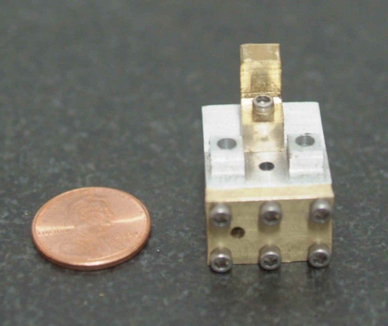
Last night and today I made the first head.  I still need a 1/16" endmill to finish a couple of minor operations, plus a 1/8" reamer, but this is it in essence:


As can be seen, lots of holes to drill in 4 of six sides.  On the top are 7 holes: 4 through hols for mounting to the cylinder, one tapped hole in the center for attaching the rocker bracket, and the two holes on the little "plastforms" for the pushrods.

On "front" you can see 9 holes:  6 for attaching the valve cover, two holes for the valves, and one hole giving access to the cylinder.  I still need to connect this hole to the right valve hole with an air passage, hence the need for the small endmill.

The bottom side has two holes that open to the cylinder.  On the left it opens very slightly to the rear of the left (input) valve hole. On the right it joins with the small hole in the front.

The right side, a small exhaust hole joints to the right valve hole.

I didn't understand how the valves worked until I had made the head and understood the interconnections of the air passages.  While the plans seem accurate, there is very little in the way of explanations or assembly instructions.  The valving works as follows:

1) The two valve holes are counter bored and will contain a ball bearing that is larger than the inner part of the bore.  When the pushrod for a hole is raised, the ball seals that hole, blocking any air passage.  The left hole is the input side.  The air inlet in the valve cover opens to this hole.  When the pushrod descends (pushed by the rocker arm), it pushes the ball outward permitting air to enter the cylinder bore.

2) Conversely, the right ball valve prevents are from leaving the cylinder until its pushrod descends.  Then the piston's upward motion pushed air through the right bottom hole, into the lateral hole, through the small air passage, into the right valve hole, past the valve ball, and out the exhaust hole.

Obviously the rocker arms must be out of phase by 180 degrees so that one valve is shut while the other is open.

The valve cover was made next.  I started with a 1/4" piece of brass plate, but mistakenly milled it to 1/8" thickness before milling the countersinks for the mounting screws.  I don't have a set of parallels that will allow me to hold it securely to mill these now, so I will likely throw this one out and make 5 more.  The inlet hole should be a bit further to the right as well.  In any case, here's how the head looks with the cover attached:


The hole in the left center is the inlet.

I then made a rocker arm bracket, but I'm not very happy with it either.  The top can be optionally rounded over with a file or corner rounding bit, but I made it slightly too thin so that the cross hole is not centered.  Once again I think it's a throwaway.  In any case, this shows how it mounts to the head:


Offline chuck foster

  • Sr. Member
  • ****
  • Posts: 334
  • Country: ca
Re: Another Halo
« Reply #44 on: October 01, 2009, 08:45:11 PM »
i have a question about this engine.
liney offers this engine as just plans ($29.00) or you can buy a machinists kit ($98.00) that has all the fasteners,bearings and metal. now my question is, is the machinists kit worth the extra bucks??

i want to build this engine but i won't be able to start building till after the new year.

chuck  :wave:
hitting and missing all the way :)

skype:  aermotor8

former hmem member

bogstandard

  • Guest
Re: Another Halo
« Reply #45 on: October 01, 2009, 09:51:29 PM »
Chuck,

If you have a look at my post,

http://madmodder.net/index.php?topic=1539.0

The first picture you come to shows the engine fasteners pack. The sectioned package on the right.

Then you will have all the materials as well. It is up to you whether it is easy for you to source the parts and materials yourself, or take the easy way out and have everything to hand.

I have attached the material list from the plans to show you what you will actually get for your extra bucks.

If you do have a problem sourcing materials, it looks to be a good buy.

BTW, the tools don't come in the pack.

Bogs
« Last Edit: October 01, 2009, 09:54:57 PM by bogstandard »

Offline kvom

  • Hero Member
  • *****
  • Posts: 520
Re: Another Halo
« Reply #46 on: October 01, 2009, 09:58:33 PM »
I bought the plans and fasteners, but not the materials.  There are a lot of 2-56 screws of different lengths, plus lots of other bits.  I think I would have spent a lot of time trying to figure out what I needed, then actually getting them.

Offline kvom

  • Hero Member
  • *****
  • Posts: 520
Re: Another Halo
« Reply #47 on: October 04, 2009, 10:50:25 PM »
Yesterday and this morning I had high hopes of finishing 5 cylinder heads.  I had milled the profiles, spot drilled all 18 holes on each, and had drilled the 4 though mounting holes on each as well.  The first task this morning was drilling the 2 valve holes.  The plans call for a 5/32 drill, but mine is missing so I decided to use the nearest number drill (#23).  This hole is drilled to a depth of .400", and then a #8 (.200 nominal) is used as a counter bore.  Unfortunately, when i did the first hole with the #8, there was no swarf.    After some investigation, I found that the tip of the #23 had broken off halfway, and somehow this resulted in oversize holes.  Effectively, all 5 heads were now ruined.  I was not a happy camper, although I had managed to refine the machining process so that I had wasted only 3-4 hours on all 5 rather than the 3-4 hours I spent making the first one solo.   

The other sad thing is that I had two #23 drills; the good one wa sitting in the space 5/32 in the drill index, and had I used that one all would be well.

Rather than restart the heads immediately, I decided to work on the valve covers.  A couple of hours work resulted in a satisfactory result:


Nothing too difficult in machining these, given a vise stop and a DRO.

bogstandard

  • Guest
Re: Another Halo
« Reply #48 on: October 04, 2009, 11:16:33 PM »
Nice one Kirk. It is coming along very nicely

This is one area I will be differing from yours. Instead of the tube spikes (real nice quality, and supplied in the kit of parts), I will be making rigid manifolds and flanges. It will be the same for the exhausts, instead of just a hole in the side of the head, mine will have exhaust stubs. It is all to do with making ones engines unique.

John

Offline kvom

  • Hero Member
  • *****
  • Posts: 520
Re: Another Halo
« Reply #49 on: October 06, 2009, 04:24:40 PM »
I too was thinking of something other than a little hole for the exhaust, but it will be an "add-on" once the engine runs.  As for a rigid manifold, I suspect I could still use these flanges as long as the input pipe fits the 6-32 threads.  That too would be an add-on.

Yesterday I started making the rocker brackets, and today I drilled the holes.  I'm still waiting for my set of O/U reamers to arrive; when they do I can ream the cross hole .124".


I also finished the milling part of a set of new heads, but didn't feel up to the marathon of drilling they need, so I set them aside for another day.

Then started on the bearing carrier.  I had a piece of aluminum that just needed a bit of turning on the lathe to arrive at this:


The left side is turned to 1" diameter so that it would chuck accurately in the soft jaws on the rotab.  The right end was faced; it's diameter is about .200" larger than the final diameter of the carrier.  Then I invoked Marv Klotz's flywheel program to get parameters for milling the spokes.  Everything is drilled/milled .150" deep or more:


Once I obtain the 3/8" under reamer for the center hole, I will turn the outer diameter on the lathe and part off the carrier at the specified .125" thickness.  I did countersink the mounting holes after the picture was taken as they use flat head screws.