After looking at this problem, the adding of 9mm of extra height between the upper frame and the lower frame, I've come to the conclusion that I'm going to have to live with it. I worked on the rotating assembly for the last couple of days and didn't accomplish much. Let's look at my version of an 800 pound gorilla.
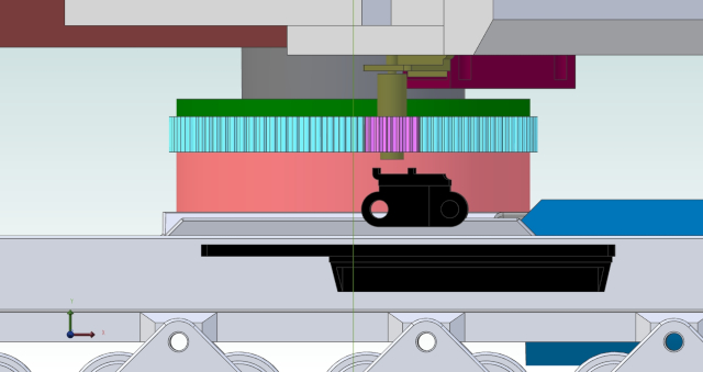
What you're looking at is the heart of this machine, it's what I call the rotating assembly. The major players in the rotating assembly are the following:
1) The upper center frame, that's the dark grey piece in the upper center. The dark brown piece is one of the upper frame rails, these rails are bolted to the upper center frame and support everything on the top half of the machine. Inside this part is where the slip-rings that feed power to the main drive motors live.
2) The slew gearmotor, that's the olive drab object. It's a repurposed 3D pen extruder drive.
3) The slew motor clamp, it's the dark purple bit. This keeps the slew motor in place, and allows about 1mm of motor adjustment for pinion mesh.
4) The slew gear pinion is the light purple object in the center. The slew gear pinion is a modified 14T GT2 timing belt pulley. Numbers 1-4 make up the top half of the rotating assembly.
5) The slew gear is the cyan colored object behind the slew gear pinion. Not shown is the slew bearing, it lives inside the slew gear, the inner race of the bearing is clamped to the upper center frame. The outer race is a press fit in the slew gear.
6) The pinkish object is the slew gear spacer. The clamp that holds the inner race of the slew bearing to the upper center frame lives in a space inside this spacer. Six M3 bolts will keep the clamp attached to the upper center frame.
7) The dark green object above the slew gear is the slew gear clamp. Six M3 bolts will go through the slew gear clamp, the slew gear, and the slew gear spacer, to keep these parts firmly attached to the main frame. (That' the light grey object at the bottom.)
In real life, what you are looking at is MAYBE 100mm wide by 50mm tall. The slew gear pinion is a modified 14T GT2 timing belt pulley. I initially thought that I could eliminate the flanges on this pulley and gain about 11mm of space. Not so much, there are still 2 problem areas.
Problem area #1 - There is about a 1mm gap between the dark purple slew motor clamp, and the dark green slew gear clamp. No matter where it is in its' rotation, about 2-3mm of the slew motor clamp overhangs the slew gear clamp. No extra room here to eliminate.
Problem area #2 - The black object directly below the slew gear pinion is a track plate. Twice in its' rotation the slew gear pinion will swing over the track plates. Only about 1-2mm of the pinion will swing over the plate, but it does swing over it. There's currently about 2mm of clearance, again nothing extra to eliminate.
Like I said, I spent a couple of days working on this and other than making some pretty pictures I didn't get much done.
Sooooo.... PICTURE TIME!
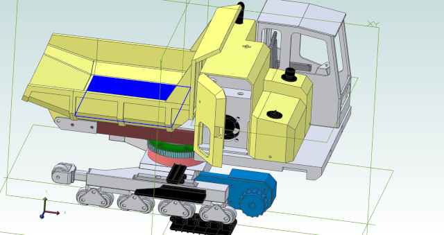
Ignore the dark blue in the dump bed, I didn't realize I had a surface selected when I exported this image.
This is another, and better, view of what's under the hood in the engine bay an tank areas. It's a cross-section view with all but about the lower 20mm of the engine bay and tank walls removed.

I just now noticed that the work platform in the foreground is not correct. The angled part of the platform should be to the front. This is a 2 piece assembly, and I'm going to have to remember to build them as mirror images, not duplicates like they are now.
Don


