Rather than hijack Petes thread and figuring this might have wider interest I started a new thread.
Having pulled my drill stand to bits and pressed the gear out, how to go about 3D modelling it and see if it can be improved for 3D printing. The straight cut teeth have very little radius at the root so can see how you could shear a tooth quite easily. Whilst looking at my gear I also noticed the witness mark from the return spring and that it was slowly ripping the boss apart when under load.
 Designing Pete's Dremel Gear.
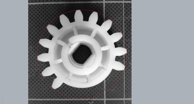
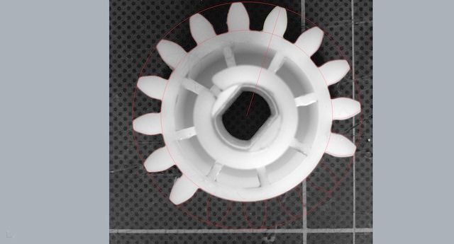
For me doing something like this and being unsure of the gear tooth profile, since it doesn't seem critical I take a picture and import into my CAD package. Measure the gear and get some reference dimensions, the red outer diameter circle, then scale the gear to as near a fit as you can. Next job is to approximate the tooth profile.
 Designing Pete's Dremel Gear.
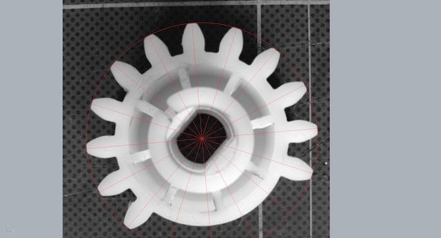
Confirm the tooth number, the gap in this gear is intentional, so it's a 16 tooth gear with only 12 teeth.
 Designing Pete's Dremel Gear.
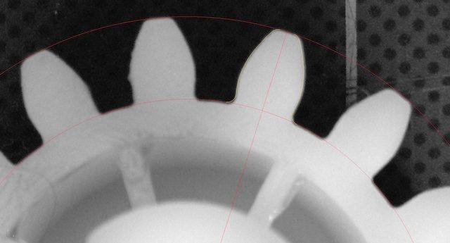
I opted to just try a couple of circles as thats quick and easy to do, then just tweak the point where they overlap. Once happy trim the circles with the inner and outer tooth diameter circles.
 Designing Pete's Dremel Gear.
That should leave us with something like this. I added fillets of 0.5mm top and bottom and then mirrored the profile to get a single tooth outline. Once thats done and your happy having taken measurements from a gear tooth to confirm dimensions generate a full set of 16 teeth (I can't generate 12 of 16 so it's easier to generate the lot then delete 4)
 Designing Pete's Dremel Gear.
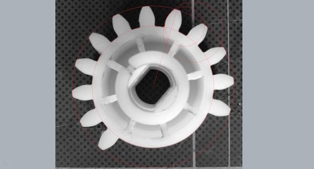
Sorry about the red lines, they show up much better at higher resolution. You can really see the parallax error from the photo now and this is why we use CAD generated circles and the profiles are checked against real world measurements.
 Designing Pete's Dremel Gear.
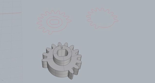
Now we have trimmed and joined our lines we will be able to extrude solids from these curves and use them to join and in the case of the bore, delete a profile to generate our model. We now have a working gear with the boss in this case increased by an extra 1mm radius for strength.
 Designing Pete's Dremel Gear.
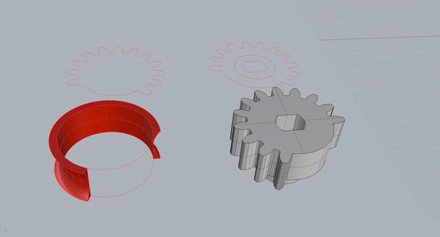
As the rack bar is 16mm diameter I make an 18mm section to add as infill to the gears. At this point I had problems with boolean operations so ended up to the cutting and splitting manually.
 Designing Pete's Dremel Gear.
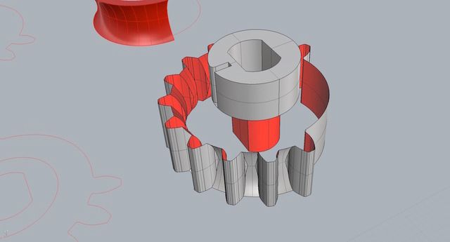
I exploded the gear I just made and removed top and bottom faces and brought in the curved surface to do the cutting of the gears. Then its sort of reverse and use the trimmed gears to trim the curved surface to get the finished profile.
 Designing Pete's Dremel Gear.
I'm now ready to add the top and bottom surfaces back to the gear and complete the work.
 Designing Pete's Dremel Gear.
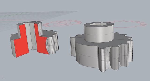
Finished gear and section gear on the left to show the new tooth root profile. All thats left is to export to GrabCad the STL file and it's up for you lot to have a look, try printing or modify the STL file as you wish.
https://grabcad.com/library/dremel-work-station-replacement-gear-1

