Author Topic: Project ... Myford M type lathe  (Read 19119 times)

Offline Eugene

  • Full Member
  • ***
  • Posts: 150
  • Country: gb
Project ... Myford M type lathe
« on: August 17, 2014, 05:06:32 PM »
The title says it all really; this will be a medium term project to get a 1946 Myford lathe up and running with a good selection of tools and ancillaries. I've given myself until Jan 1 to get the job done; at that point I either take it round the back of the barn and stick a round from a big bore Webley in it's ear or move it out of intensive care and into rehab. Pic below from the Myford publicity dept.


Post retirement I wanted to develop my interests in amateur gunsmithing and automata, so a lathe was an obvious necessity. The choice lay between "Any old British Iron" or a Chinese machine composed of old bean tins, bicycle frames, sand and bad paint. The M type has an interesting history being the standard model makers machine prior to WW II, and then being issued in large numbers to the armed forces. REME workshops, RAF bases and HM ships and submarines all had them; some folk have even traced which ship their ex RN machine came from. I got mine off Ebay for a princely £300 plus a trip from Wales to Sheffield.  I'm still unsure if I made the right choice ... neither option is without it's difficulties especially for the beginner, which is definitely me.

The m/c came in good basic condition (plus a coat of rubbishy black paint) the original guards, motor, stand were all present and correct. The bed ways showed rust speckles but you cant get a .0015 feeler gauge under a straight edge at any point nor can you see daylight. What it didn't have is a much longer list than what it did. Viz.....four jaw chuck, fixed and moving steadies, face plate, complete change gear set (about one third present), cutting tools or multiple tool holders. As a novice I didn't realise the significance of all this and thought getting the bits and bobs would be simple and relatively cheap.  :doh:

My first efforts at turning a bit of printer rod were awful; the tool climbed all over the workpiece, the finish was terrible, and lots of noise accompanied proceedings. I found accurately setting the tool height to be impossible using all the usual methods advised on the 'net. Lining the bit up to a centre, the nearest I managed was about .030" off; up or down please yourself. The steel rule trick was another fiasco; hopeless, so I determined the exact centre from the bed with a second hand Microball height gauge (£20 off Ebay worth it's weight in gold) and set the tools with that. I reckon I'm just about spot on now and never get even the trace of a pip on a facing cut. Result.

I soon discovered that I was a chump at hand grinding HSS tools. With great help and advice from Jenny at JB Cutting Tools I have used carbide inserts for virtually all the development work; under the right conditions they work a treat. Under the wrong ones they chip, break and die which for me is a good sign to stop what I'm doing and have a re-think. Even so I still couldn't take a cut over .010" without chatter; if I stayed within that limit I was usually OK and got a very nice finish, anything more bust the tool as chatter kicked in. I then started to work back from the tool bit, to the top slide gibs, to the cross slide gibs, to the carriage gibs, carriage stop, you name it, looking for sloppiness ... nada, nothing improved matters.

It slowly dawned (I know, I know) that if I fed the tool in with the leadscrew handle and kept the pressure tight on, the chatter diminished; ease off and chatter returned. I tightened up the phos. bronze bearings according to the book, but I still couldn't get any forrader and the scrap bin was filling up with inserts. The problem it seemed to me must lie in the headstock bearings and was probably end float. This was quite a leap for mankind because I'd never even heard of end float at that point ..... now I'm an expert! There is a collar on the rear spindle end which is supposed to tighten up an internal thrust bearing; I did that and still got no improvement but there was a clue something was amiss and needed rectifying. If I turned the collar finger tight as hard as I could and ran the lathe the bearing got hot very quickly. Time for invasive surgery..... When I took the spindle and bearings out I saw this ....


At first I was really depressed, they looked pretty gruesome, but I have access to an ultrasonic cleaning unit and after a good blast virtually all the black crap was gone off the spindle. A bit of gentle work with steel wool and the difference in appearance was remarkable without any measurable dimensional change. I'd had a bit of a head scratch in the meantime and formed the theory that the scoring was preventing any axial movement when the thrust collar was tightened up and thus allowing end float, but pressure from the tool overcame this and pushed the spindle against the internal thrust bearing. What was needed was a second, but very thin, thrust bearing on the outboard end of the left hand bearing to pull things together. And here it is ...


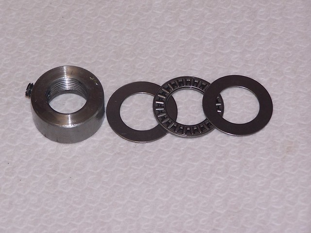
It's an Imperial size, 3/4" ID by 1.25" OD and fits exactly! On reassembly and oiling the whole shooting match slid together as sweet as nut, much nicer than before............... and the cursated chatter has gone, departed, it is no more, finito, ab est  :D It sits in the recess between the threaded collar and the bronze bearing nut as if it was made for the job, and still there is a bit of wiggle room left.


.060" cuts off diameter (might be more, haven't tried) and an acceptable finish; so now I have a workable machine and it's onwards and upwards. You can't believe how long it's taken to get here, and how frustrating it's been but I feel I'm on the way now. Next stop tool grinding and tool holders with incremental height setting.

Eug


« Last Edit: August 17, 2014, 05:38:43 PM by Eugene »

Offline Henning

  • Full Member
  • ***
  • Posts: 136
  • Country: no
  • All the kit and no clue!
Re: Project ... Myford M type lathe
« Reply #1 on: August 18, 2014, 04:30:27 AM »
Nice post! I can't wait to see how you get on  :mmr:

Now, how about a current picture of the whole lathe?
Henning

Just because i can't, doesn't mean i shouldn't?
Tool- lover, with a collection to show for it!

Offline John Hill

  • The Artful Bodger
  • Madmodder Committee
  • Hero Member
  • *****
  • Posts: 2016
  • Country: nz
Re: Project ... Myford M type lathe
« Reply #2 on: August 18, 2014, 04:59:46 AM »
Seems you have made good progress Eugene.   

I notice you have also posted on the Drummond usergroup,  has anyone over there been able to help with parts?

My 1908 Drummond arrived with everything except the treadle and the flywheel, everything else was in the box including the quaint wood block travelling steady.  I made one change gear for it which was not really difficult.

Looking forward to see pictures of your progress with this machine!
From the den of The Artful Bodger

Offline Eugene

  • Full Member
  • ***
  • Posts: 150
  • Country: gb
Re: Project ... Myford M type lathe
« Reply #3 on: August 18, 2014, 07:20:21 AM »
John,

The folks in the Drummond forum have been really helpful; one chap sent me a few taper pins I was short of without any charge, and you can't get better support and encouragement than that. Buying M type bits has been a mixed experience however, so I'm pretty wary now and know who to keep clear of. I've got to the point where what I need can probably be either adapted from non M type parts or made from scratch; hence making a start on an ally smelter and foam cutter.

The best recent purchase was a nice big face plate; with it I can more or less duplicate a four jaw chuck using holding devices of  my very own design. Imagine the chagrin when I saw in an old reference work that these things had been known for years and were called faceplate screw dogs. I always thought Faceplate Screw Dog was a dodgy Comanche character out of "Lonesome Dove", Blue Duck's deviant brother perhaps.  :)

here they be ... the very first parts I've ever made with a lathe, other than a big bolt hacked about and made into a tool post for the cross slide. Chuffed.


Eug

Offline vtsteam

  • Global Moderator
  • Hero Member
  • *****
  • Posts: 6466
  • Country: us
  • Republic of Vermont
Re: Project ... Myford M type lathe
« Reply #4 on: August 18, 2014, 08:00:16 AM »
Hey great thread Eugene, definitely will be following  :coffee: :coffee:.

That faceplate is a beauty -- it has 8 opposed radial slots, which really helps with clamps and they go very close to center -- which also is a great feature.

I was used to my homemade  faceplate on my Gingery lathe when I brought the Craftsman 12" lathe. It had no faceplate and I purchased one. However the hub is very wide and the slots stop a fair distance short of center because of that. What this means is that none of the many accessories I made for the Gingery faceplate work with the new faceplate, including the driving dog.

Since you don't have many accessories or change gears, I'd like to recommend the Gingery books to give you some ideas -- using your faceplate the books show making a 2 jaw chuck (very handy), a 4 jaw chuck, dividing head, change gears, bell chucks, boring bar, etc. all VERY simply compared with many other project books. There are some fine devices you can build with detailed plans elsewhere, but those can take months to complete and require special tooling, and difficult to obtain materials. I think the genius of the Gingery books is that the projects are quickly and easily do-able with everyday materials,while learning how to machine. And they teach you the history of precision tool development in the process. They also start from nothing, rather than a well equipped shop.

Anyway, they're worth a read, and aren't expensive.

Great project!  :thumbup:  :beer:
I love it when a Plan B comes together!
Steve
https://www.youtube.com/watch?v=4sDubB0-REg

Offline vtsteam

  • Global Moderator
  • Hero Member
  • *****
  • Posts: 6466
  • Country: us
  • Republic of Vermont
Re: Project ... Myford M type lathe
« Reply #5 on: August 18, 2014, 08:16:45 AM »
Does your tool holder have a height adjusting screw? -- I don't see one in the photo. If not you could add one. Just a vertical screw about 6mm threaded through the block that bears against the topslide. It adds both stiffness to the tool, holder adjustment ease, and repeatable height setting.
I love it when a Plan B comes together!
Steve
https://www.youtube.com/watch?v=4sDubB0-REg

Offline Eugene

  • Full Member
  • ***
  • Posts: 150
  • Country: gb
Re: Project ... Myford M type lathe
« Reply #6 on: August 18, 2014, 10:16:07 AM »
Steve,

Thank you for the Gingery Ref; I already have the series and find it inspirational and good fun. There are some things I'd like to make such as the two jaw, but I'm holding back until the lathe is running well with a modest set of tools.

The tool holder doesn't have an incremental adjustment and is one reason it's hard to set an accurate height; you need three hands. The existing holder is case hardened to a fair depth so drilling and tapping would be problematical unless I took a chunk out of each face with a diamond tool in a Dremel or the like, neither of  which I have. :( The set I propose to make will certainly have adjusting screws; I'm already chopping up bits of steel for the blocks and I'll colour case harden them too just for swank.

Eug


Offline vtsteam

  • Global Moderator
  • Hero Member
  • *****
  • Posts: 6466
  • Country: us
  • Republic of Vermont
Re: Project ... Myford M type lathe
« Reply #7 on: August 18, 2014, 10:31:44 AM »
Eugene, the main reason I mentioned the adjustment screw is actually to add stiffness to the toolpost -- it makes a big difference to chatter -- and particularly when parting.

It might be possible to drill a hole with a masonry drill. The problem would be threading -- but a serviceable possibility is just a length of threaded rod through the hole with nuts on either end, top and bottom to pinch the toolholder between them.

If you want to do it fancy, turn a short press-in flanged tubular nut to fit the hole at the bottom, put it in ice water to shrink, press it in with the vise, tap it, and add a conventional adjustment screw.

I love it when a Plan B comes together!
Steve
https://www.youtube.com/watch?v=4sDubB0-REg

lordedmond

  • Guest
Re: Project ... Myford M type lathe
« Reply #8 on: August 18, 2014, 10:34:42 AM »
The case hardening is easy to deal with no diamond tools required

Ok here's how get it good and hot a nice red will do and let it cool slowly very slowly

This will soften the CH after you have done the work just reheat to red again and quench in water that will restore the CH

Of course you will need to do a clean up after

Btw the case hardening compound you can buy now is junk with a capital J

Try to get some proper Kasenite but it will be difficult as the good stuff had traces of cynanide in it and our nanny state or EU has banned it

Stuart

lordedmond

  • Guest
Re: Project ... Myford M type lathe
« Reply #9 on: August 18, 2014, 10:38:16 AM »
Vtsteam
The CH will only be a few thou deep anyway so threading will not be a problem after softening

Stuart

Offline vtsteam

  • Global Moderator
  • Hero Member
  • *****
  • Posts: 6466
  • Country: us
  • Republic of Vermont
Re: Project ... Myford M type lathe
« Reply #10 on: August 18, 2014, 01:47:48 PM »
Ah, Stuart thanks. I thought about heating it to soften, but forgot about the fact it could be done twice and hardened again.  :loco:
I love it when a Plan B comes together!
Steve
https://www.youtube.com/watch?v=4sDubB0-REg

Offline Eugene

  • Full Member
  • ***
  • Posts: 150
  • Country: gb
Re: Project ... Myford M type lathe
« Reply #11 on: August 18, 2014, 07:11:06 PM »
Steve, boys, thanks for the input.

I'm not going to touch the existing tool holder, it is what it is, and I don't want to remove any authenticity if it can be avoided. It has some cyanide type case colours left that look quite nice. There are now eight blocks of EN 36 bludgeoned into shape that are waiting for me to finish them off (need to work out how to form HSS tools first)  :scratch: so that should be enough.

Steve, I don't quite see the adjustable screw adding to tool post stiffness on the M type. The post is 1.25" dia. and cast integrally with the top slide, so basically bomb proof. An M 4 screw isn't going to add much, unless there is something I'm not seeing. As I said, all the eight new holders will have incremental adjustment via a screw anyway, and once the set is completed I'll have what will be virtually a QCT arrangement, but with the addition of ad lib indexing. 

Thanks for the support lads, I'll be off air for a while beating a (insert derogative adjective of choice) Chinese made "Record" bench grinder into submission; it's got more wobbles than Dolly Parton drilling a concrete road.

Eug


Offline vtsteam

  • Global Moderator
  • Hero Member
  • *****
  • Posts: 6466
  • Country: us
  • Republic of Vermont
Re: Project ... Myford M type lathe
« Reply #12 on: August 18, 2014, 09:49:21 PM »
I have exactly the same setup Eugene -- same thickness toolpost, and believe me it does make a difference. The screw comes down and bears on the topslide toward the center of the lathe -- in other words, if it is 1/2" forward of the post, your post now acts like it is 1-3/4" thick instead of 1-1/4" and your effective tool overhang is also reduced by the same 1/2".

Chatter is a vibration due to flex in your whole tool support system. While it is unlikely you will bend a 1-1/4" post, is a different matter to harmonic deflection of the components which happens with relatively light forces. And parting off will really let you know the value of stiffness in a lathe's components. Up to you, of course.
I love it when a Plan B comes together!
Steve
https://www.youtube.com/watch?v=4sDubB0-REg

Offline Eugene

  • Full Member
  • ***
  • Posts: 150
  • Country: gb
Re: Project ... Myford M type lathe
« Reply #13 on: August 19, 2014, 02:45:08 AM »
Steve,

The harmonic thing makes sense, I see it now.  Even with the new set up there is a certain point on an unsupported workpiece about 1 1/2" from the chuck jaws where I get a tiny bit of chatter; I'd put it down to harmonics without thinking any further. I hadn't given any consideration to where the adjustment screws will go relative to the tool end ..... I will now!

Thanks

Eug

Offline vtsteam

  • Global Moderator
  • Hero Member
  • *****
  • Posts: 6466
  • Country: us
  • Republic of Vermont
Re: Project ... Myford M type lathe
« Reply #14 on: August 19, 2014, 07:13:58 AM »
Eugene, the same thing can be had by putting a packing piece under the tool holder -- like a super thick washer -- the only problem is it needs to vary in height depending on the height of the cutting tool, or the tool itself can be shimmed in its holder -- however, the inconvenience of shimming is why multiple holders and the adjusting screws in the holders were invented in the first place

If you look at other styles of QCTP you'll notice the best of them use a BIG block of square steel as the toolpost -- usually with dovetail ways. This block has much greater cross sectional area than our round posts -- both because it is thicker, and because it is square. That whole block sits on the topslide. BIG footprint.

But if we properly arrange the adjustment screw on our style toolpost, it can act as if it has a much larger section, too

This was brought home to me the other day when I quickly adjusted my parting tool holder by sliding it up about an eighth of an inch on the post and tightening the holding bolt rather than using the adjusting screw -- bad idea!  About 30 seconds into the cut I was seeing big problems and finally actual visible flex. Quickly retracting the tool before anything broke, I was like "What the he.....?"

It didn't take me too long to figure out that I should have bottomed out that screw. When I did, things returned to normal and I parted off without problems.

That's why I mentioned parting especially to you -- it was a pretty fresh subject!

I love it when a Plan B comes together!
Steve
https://www.youtube.com/watch?v=4sDubB0-REg

Offline awemawson

  • Global Moderator
  • Hero Member
  • *****
  • Posts: 8970
  • Country: gb
  • East Sussex, UK
Re: Project ... Myford M type lathe
« Reply #15 on: August 19, 2014, 07:51:13 AM »
Without drilling holes in your tool block, you can prove the point with a small machinists jack placed between the holder and the top slide. Nip it up and try the difference. If you don't have a small enough one use the old trick of a suitably sized nut, bolt and lock nut.
Andrew Mawson
East Sussex

Offline Meldonmech

  • Hero Member
  • *****
  • Posts: 933
Re: Project ... Myford M type lathe
« Reply #16 on: August 19, 2014, 11:00:01 AM »

   Hi Eugene, restoring machinery is an interesting and rewarding activity.  You appear to be on the right track,

                                           Good Luck
                                                                 Cheers David

Offline John Hill

  • The Artful Bodger
  • Madmodder Committee
  • Hero Member
  • *****
  • Posts: 2016
  • Country: nz
Re: Project ... Myford M type lathe
« Reply #17 on: August 19, 2014, 04:06:59 PM »
I made a Norman style tool holder for a Grayson lathe I have and it works well but I am sceptical that the adjusting screw contributes anything much to rigidity.

The problem is that to be truly effective the adjusting screw would have to be under or very close to the tool holding passage which is not easy to arrange.

I really doubt there would be room to fit any sort of screw jack under the tool holder.

But the adjusting screw does make setting the tool height a piece of cake, adjusting screw and an easy to use gauge.
From the den of The Artful Bodger

Offline vtsteam

  • Global Moderator
  • Hero Member
  • *****
  • Posts: 6466
  • Country: us
  • Republic of Vermont
Re: Project ... Myford M type lathe
« Reply #18 on: August 19, 2014, 06:53:35 PM »
Sorry you;re skeptical, John but that's out of my control. It's a demonstrable fact here, I'd post photos but I'm getting tired of trying to convince people things any more. I've lost the energy for it.
I love it when a Plan B comes together!
Steve
https://www.youtube.com/watch?v=4sDubB0-REg

Offline Fergus OMore

  • Hero Member
  • *****
  • Posts: 1012
  • Country: england
Re: Project ... Myford M type lathe
« Reply #19 on: August 20, 2014, 04:34:55 AM »
Agreed about photos because unless your expectancy of model engineering NEEDS pretty pictures, few will get very far.

I recall doing a City and Guilds in Motor Vehical Repair and no one posted pretty pics but had to list -like a knitting pattern precisely what was done and intended.  If one cannot read a drawing - tough.

As far as the old Myford is concerned, restoration really follows a traditional path of getting a flat base from the probably undulating one from a lifetime of service. At some point, the book says that it should be machined and then scraped or ground. All my restorations started with a Blancharding to get a set of reference tools.  Blancharding is cheap, not the worlds best or most accurate but may cost under 50 pounds.

Really the tooling mentioned about archaic tool holders etc is- more than dated and I would suggest that both George Thomas and ' Martin Cleeve' have published vastly better stuff. Even if fabricated from steel blocks.

There is a vast amount of constructive detail in ME and MEW.

Enough for my struggles on a German Keyboard in the Austrian Alps

Norman

Offline DavidA

  • Hero Member
  • *****
  • Posts: 1219
  • Country: gb
Re: Project ... Myford M type lathe
« Reply #20 on: December 31, 2014, 11:27:57 AM »
Eugene,

... I've given myself until Jan 1 to get the job done; ..

Did you make it ?

Dave.

Offline Eugene

  • Full Member
  • ***
  • Posts: 150
  • Country: gb
Re: Project ... Myford M type lathe
« Reply #21 on: December 31, 2014, 05:12:28 PM »
I've given myself until Jan 1 to get the job done; ..Did you make it ?


Near enough.

We have an elderly friend who is grievously ill so the time given to him is not begrudged, but it has slowed me down a bit.  So there is some way to go yet, but I'm confident it's all doable.

The M type has been an equal mix of fun and frustration but In spite of some the aggronoying bits I've enjoyed what I've done. I spotted a long bed version for sale recently that came with a very comprehensive accessory kit and got it for not much money, so I've got a lot more bits and bobs now. It's not as pristine as my first one and had no motor, countershaft or stand; so another project! I've astonished myself at just how accurately the original M type can work; with the top slide set over I'm down to tenths.

One of the difficulties I've faced is grinding HSS tools (from blank) so I made a grinding rest which was rubbish .... mark two now under construction. When that's done I need to get the wood butchery fired up to make better use of the available space by building a workbench similar to the one VTsteam (Steves) showed, and another roll top wall cabinet. The shop heating such as it is has proved inadequate; some thought required there.

That's after I've finally got rid of the (insert pejorative adjective of choice) moles in the lawn, the squirrels demolishing the bird feeders and the mice in the house roof space.  :doh:


Eug