Hi,
I just had to upgrade photobucket, I was over the 100Giga /month bandwidth. I hope nobody was inconvenienced by this!
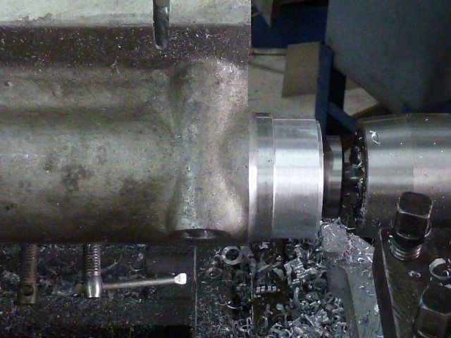
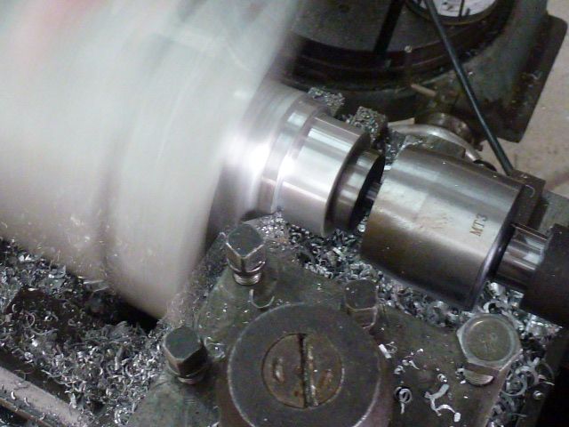
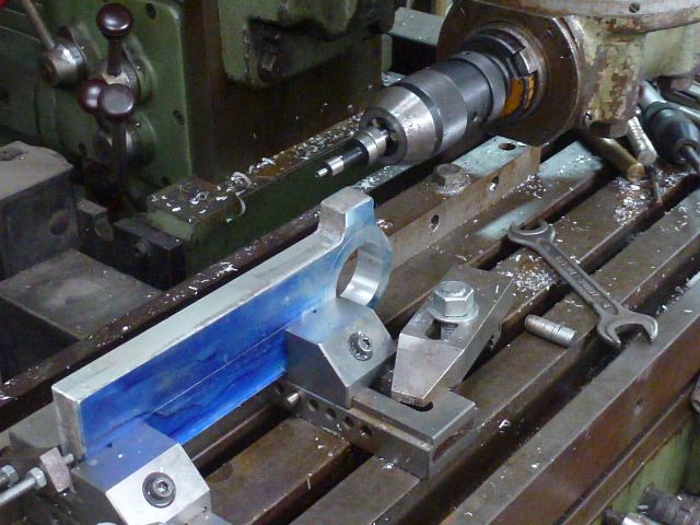
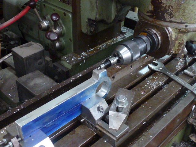
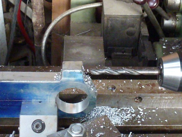
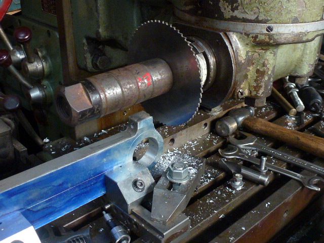
Back to turning down the "nose" of the main casting.
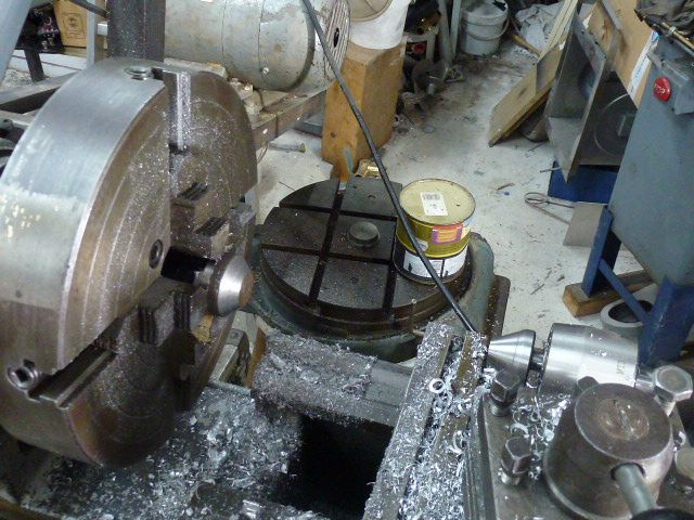
For those of you who see me as dicing with death, The casting is between centres, it's running at around 150rpm, so the loads on those two "G" clamps is pretty low. Fortunately it's not running in a division of 50 hertz so it looks like it's spinning although I can't really see it clearly! Mind your fingers!
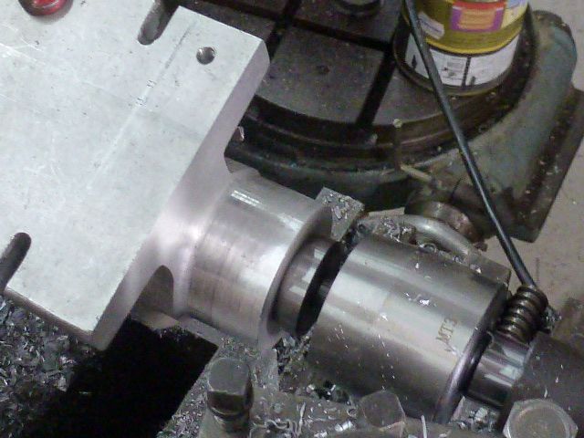
I'm using a form tool to cut a radius in the corner of the nose, the tool itself is difficult to see.
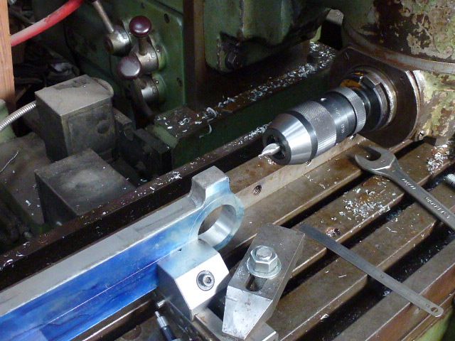
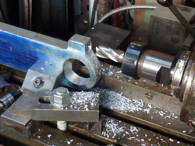
Beginning the cut on the shoulder where the banjo sits.
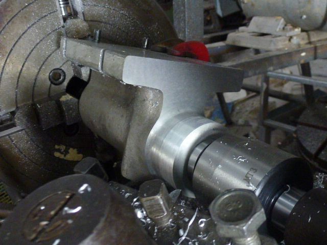
More shoulder!
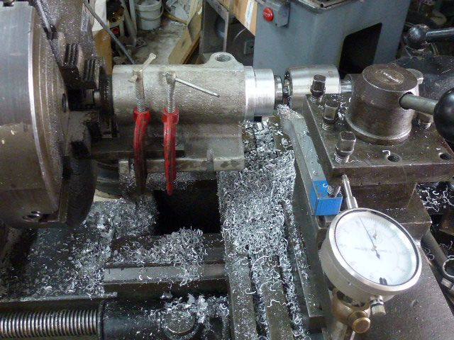
I don't have any dials on this lathe, I prefer using a "clock" it's "what you see is what you get", at least, as far as the radius is concerned!
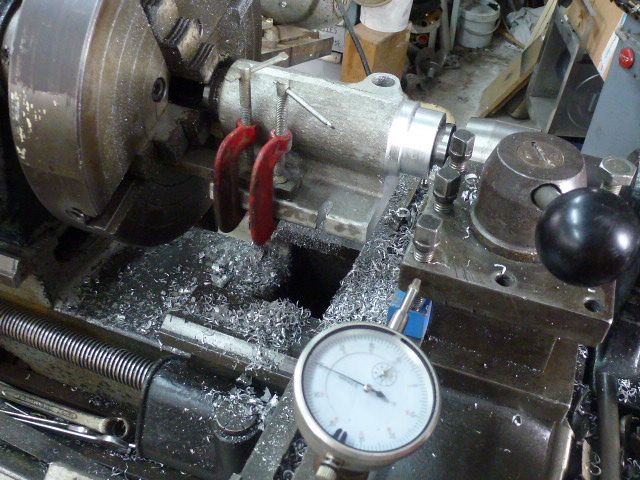
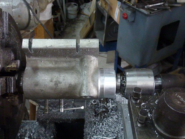
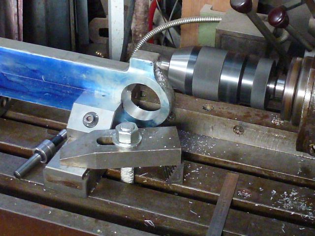
Getting close! I see that I didn't take any photos of measuring with the mike!
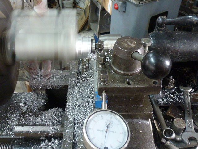
I do like action shots.
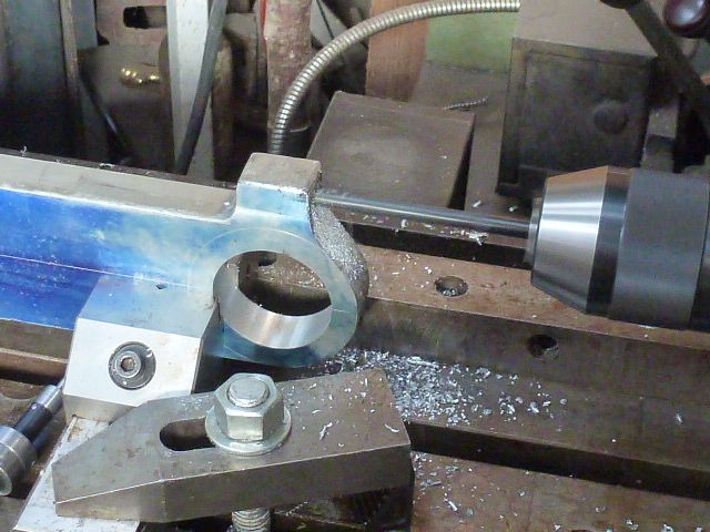
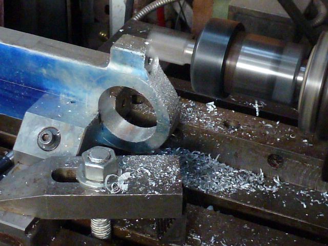
45° tool, taking of the sharp corners, hmm, it's a bit hard to see!
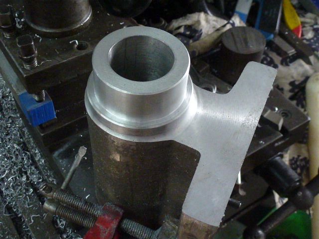
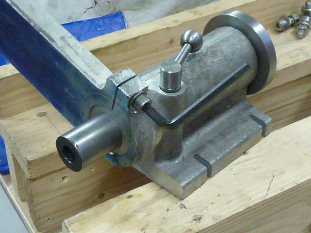
At least I got this one right! Now I can go back to the banjo.
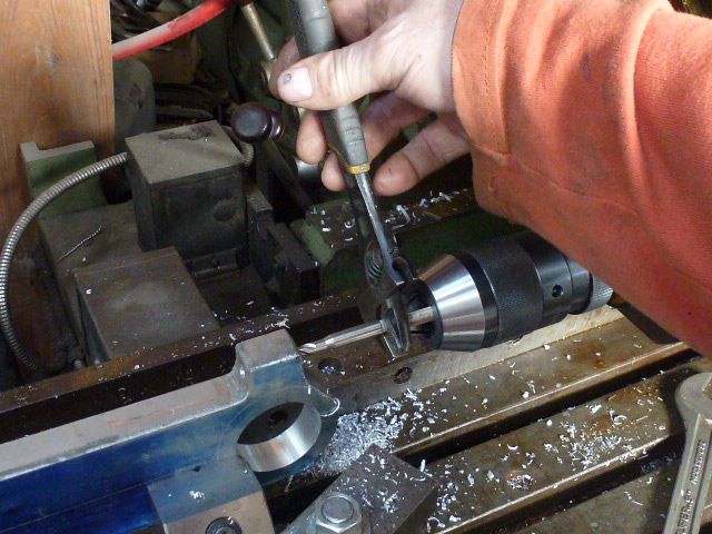
Centring the bore.
First cut.
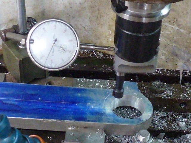
This is an imperial boring head, I find it easier to use a dial gauge to adjust, nice big dial, instead of a tiny little thing in thousands of an inch!
I bought this bore gauge set for this job, a cheepo that I had to smooth the ridges of the ends before it would work properly.
A nice sliding fit!
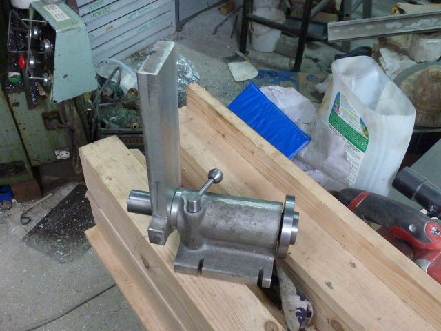
One of the nice things about this milling machine is you can also use it horizontally. Finding the centre of the thickness of the banjo.
Finding the top to place the hole for the pinch bolt.
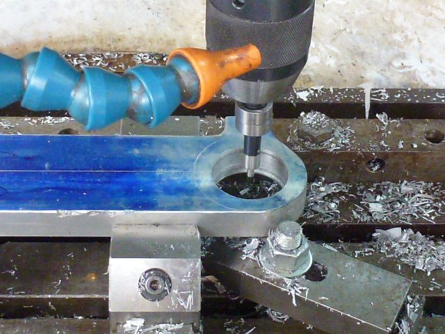
The usual suspects, centre bore.
Muppet! I had to centre bore twice, I forgot to deduct the 5mm radius of the centre finder!
Drill, 6.75mm right through, tapping size for 8mm.
Drill half way through, 8mm clearance.
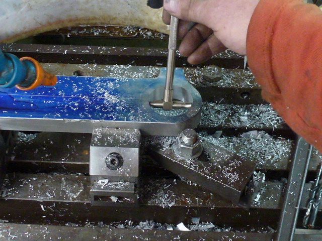
I had to tap with an adjustable spanner, I don't trust my self to power tap and you can't just switch off and let it run through, there's a serious very efficient spindle brake.
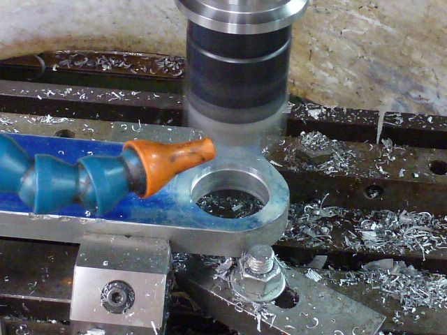
I didn't measure the cutter, a second hand one, beautifully sharp, 1mm under the 19mm marked on it!
The next on up is 22mm so I had to lift it to take the corners off as well.
I have three of these arbours, by the paint marks on them one of them is bent! They're 25.4mm the French don't know that they're using inches on some of their tooling!
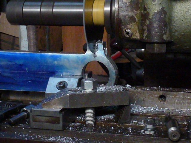
2mm slitting saw.
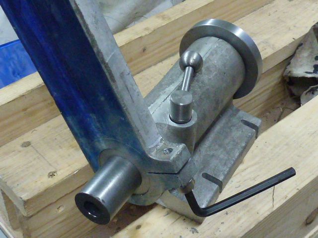
It works!
That's it for now, be back soon, regards, Matthew


